|
THE earliest model yachts had no steering gear whatsoever, and consequently
were unable to sail a good course when the wind was anywhere abaft the
beam. The first steering gears to come into use were weighted rudders,
and though these were better than nothing at all, it was not until 1906
that the first efficient steering gear was invented. With its invention
model yachting at one stride advanced from being a more or less childish
pastime to a sport calling for great skill and accuracy.
Now, in theory the main function of the rudder is not to hold a yacht
on her course, but to steer her back to her course when she is thrown
off it by a puff of wind. Actually, in practice, the helm does hold
the boat on her course, and with a good helmsman every variation in
the wind is anticipated and met, so that the yacht keeps a dead-straight
course. A straight line is the shortest distance between any two points,
and, obviously, the helmsman who sails the straightest course is going
to gain much ground on his rivals.
It would, therefore, seem to be an absolutely correct principle in models
to make the very factor that tends to throw the yacht off her course
actuate the rudder to keep her straight. Several attempts were made
to do this, and in 1906 Mr. George Braine of Kensington evolved the
steering gear for models which bears his name.
By this gear, the angle of the rudder can be made to vary in exact
ratio to the pressure of the wind on the sail. During the years that
have elapsed since its introduction, minor improvements have been made
in the pattern of the quadrant and by the substitution of a slide for
the pinrack with which early gears were fitted. The principle of the
gear, however, remains absolutely unchanged.
The method of using this gear is not covered here, and we are here concerned
mainly with the way to make it and fit it up. At the same time some
little explanation at this point may be of assistance to the builder
in making and fitting the gear correctly.
The principle is briefly that as the wind freshens the yacht tends
to head up towards the wind. In a full-sized vessel the helmsman corrects
this by giving the yacht weather helm. In the model the pressure of
the wind on the sail causes it to pull on the sheet, which is attached
to the helm and thus operates the rudder. There is an elastic centering
line to bring the rudder back amidships. As the pull of the sail must
operate through the weather sheet, the steering lines are accordingly
crossed.
The gear itself consists of a quadrant attached to the rudder-head,
a pair of pulleys, a tension slide, and an elastic centering line. The
first essential of any steering gear is that the rudder shall move freely.
To ensure this, the pintle must be properly made and fitted and the
rudder-post must not bind in the rudder-tube. Care should be taken that
no paint or varnish gets inside the rudder-tube, as nothing will cause
a rudder to bind more. Another point of the utmost importance is that
the pulley blocks must run very freely and that the steering lines must
render easily through them.
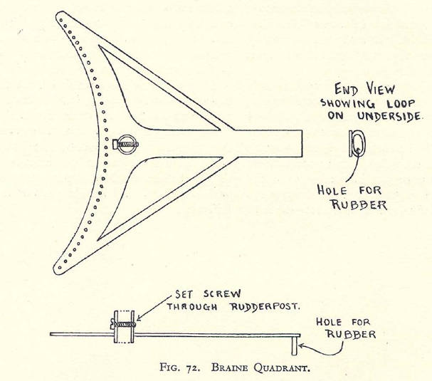
The quadrant of an A-class boat will measure about 4 in. from back to
front, and about 5 in. across. It will be smaller proportionately for
the smaller classes. The radius of the curve of the forward part is
approximately 4 1/2 in, and the holes for the hooks are spaced 3/16-in.
centres. A wire loop is hard soldered on the underside of the tail to
take the rubber centering line as shown in the end view given in the
diagram. In order to take the rudder-post, the quadrant carries a sleeve
5/8 in. long. This is hard soldered to the quadrant, and has about half
its length below it. The sleeve must be a close fit for the rudder-head.
A set screw passes through sleeve and rudder-head, and prevents the
quadrant from wringing round. It is essential that the rudder and quadrant
be very carefully lined up when drilling the hole for the setscrew,
as if the rudder is the least fraction out of central the boat will
not sail properly.
A suitable length of rubber cord is now cut off to form the centering
line. For an A-class model this will be 3/16-in. diameter. The rubber
is used double. The ends are lashed together, and the cord middled and
hooked on at the stern. It is then passed through the eye in the quadrant,
and one part passed on each side of the rudder post under the quadrant.
The quadrant will have to be taken off whilst this is being done. A
cord with a bowser is fastened to the forward end of the centering line
to allow for its adjustment. Carefully line up and put a screw-eye into
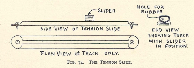
the deck to take the forward end of the centering line. The slides have
now to be put in place. In the case of a single slide, the rubber passes
through the hole in the slider, but in the case of double slides it
passes between them. In putting the slides into position, great care
must be taken that they do not give the rudder bias either way. The
slides should be so placed that when in the most forward position the
slide is within 1/16 in. of the tail of the quadrant.
The steering pulleys have now to be fixed. These should be sufficiently
far apart to ensure the leeward line remaining idle if the boom rises
somewhat in a heavy wind.
Although the use of tension slides enables the pinrack to be dispensed
with, many skippers still fit one in addition. Moreover, for certain
purposes they are very convenient. In any case this is a very simple
fitting to make.
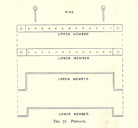
The material required is two strips of brass 3 in. wide. Bend the first
to form a bridge over the tail of the steering quadrant and just clearing
it comfortably. Bend the second to form a corresponding bridge under
the quadrant, about half way between the tail and the deck. The length
of these bridges will vary between 2in, and 3 1/2 in, according to the
size of the boat. Drill holes in the ends of the bridges to clear a
3/8-in. No. 1 screw. As the two bridges are screwed down to the deck
together, the holes must register. Screw both parts down together on
a spare piece of wood. Starting at the exact centre, drill pinholes
right across at 3/16-in. intervals. Since the two bridges are screwed
down to the deck together, it is unnecessary to sweat them together,
but it makes a rather neater job to do so. To complete the fitting,
two pins are required. These should be long enough to go through both
bridges without touching the deck. To avoid loss, the pins should be
secured by short lanyards.
This completes the gear required for Braine steering, unless it is wanted
to make provision for jib steering as well as mainsail. In such case,
an extra pair of pulleys and two quadrant hooks are needed.
When a model is fitted with Braine steering, the steering is out of
action when she is close hauled, and she relies entirely on the trim
of her sails. Although this will be discussed at length when we are
dealing with the handling of a model yacht, it must briefly be referred
to here.
Since a vessel cannot sail against the wind, she has to work to windward
in a series of " tacks," pointing first to one side of her
goal c and then to the other. To gain ground to windward, tacks must
be sailed at an angle of less than 90 degrees to the wind, and a close-winded
yacht will sail at about 4 degrees'. A boat's course is determined largely
by her sail trim, and some boats " point " higher than others.
If a boat is sailed too close, she will not " foot " (move
smartly through the water), but lose speed. Sailing to windward becomes,
therefore, a compromise between pointing and footing, so as to get the
boat the greatest possible distance to windward in the shortest possible
time.
Abbreviated extract from Daniels and Tucker - Model Sailing Craft
3rd Edition
Fuller details and plans are available to members
of VMYG on request.
|